MasterSeries Blog
Is your finite element mesh size appropriate?
The accuracy of any FE analysis is heavily influenced by the size of the finite element mesh. Large elements result in a faster analysis time but at the cost of a loss of accuracy. But a small global mesh size, while giving a higher level of accuracy, comes at the cost of analysis time. So how do you know if the mesh is correct?
How big is too big?
As a general rule, the Concrete Centre publication “How to design reinforced concrete slabs using finite element analysis” advises that the elements should not be larger than span/10 or 1000mm, whichever is smaller. While the maximum element size is dependent on the element type, these rules are a reasonable starting point, though it is possible that larger elements could be used. For complex geometries, the determination of the span length may not be straightforward, but a reasonable estimation will generally be sufficient for the initial mesh sizing.
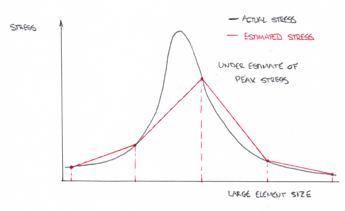
However, the above rule is a starting point and it is likely that for at least some of your models, the mesh will need to be smaller than this. The reason for this is that the results of an FE analysis are based on the nodes. The distribution of stress (and so force) within the element is approximated using the element shape function. So, if you have regions where the stress is changing rapidly, large elements are likely to lose at least some of the distribution of the stress. This may affect the accuracy of the results.
Can a mesh be too small?
Theoretically, the smaller the elements, the more accurate the analysis is. However, practically, there are inherent limits on the level of accuracy that can be achieved and there comes a point where reducing the mesh size further adds to the required time to run the analysis without an appreciable increase in accuracy. Ultimately, the accuracy of the analysis is going to be limited by the accuracy of the computer, but more importantly, the analysis time will simply become too great to be practical. The balance is to use a mesh that is small enough to give the required level of accuracy while still returning the analysis results in an acceptable time frame.
How small is small enough?
Ideally, there would be a specified element size that would ensure sufficient levels of accuracy in an FE analysis. Unfortunately, this is not the case and so the user must make an assessment of the level of accuracy given by the mesh. This is done by carrying out a convergence test.
One simplified way to do this is to half the mesh size and re-run the analysis and compare the change in the results – if the changes in the results are small, then the first mesh size was acceptable. This will potentially require several runs of the analysis with repeated halving of the mesh size to determine an acceptable mesh size. However, there is no definition of ‘small’ and so engineering judgement is required. This will require the user to carry out a validation of the results and compare the accuracy of the analysis results with the expected results.
The above approach can be useful for determining an appropriate mesh size for a global analysis but may be less useful for areas with high-stress concentrations, which may require further localised refinement of the mesh. This may require a more formal convergence test.
Convergence testing
A convergence test consists of comparing the results at a specific location within the model and examining the effect that varying the mesh size has on the result. This requires at least three runs of the analysis with three significant variations in the mesh size. Useful results for use in a convergence test would be the Wood Armer moments, principal stresses or von Mises stresses.
With the results at a specific location determined, a graph is then produced showing the result against mesh density (or number of nodes). It can be useful to look at the percentage change in the results rather than the magnitude of the results which will vary from model to model.
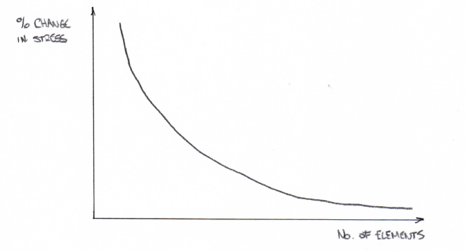
How small a change in the results is considered to be small enough is down to engineering judgement, but will depend on the model and the location within the model under consideration. More critical areas may require a greater level of convergence than less critical areas.
When doing a convergence test, it is important to avoid using a stress singularity as one of the points under consideration, since the stress (and so the subsequent force results) will continue to increase with smaller and smaller mesh sizes and so the stress at or very close to a singularity will not converge – theoretically, at a point of singularity, the stress will tend to infinity.
With experience, a formal convergence test can often be skipped and the mesh size investigated more informally by simply viewing the change in the results. But care is needed since changes in geometry, constraints or loading conditions can result in different structural behaviour and stress distributions which would require more in-depth investigation.
Conclusion
Even with auto-meshing functionality, getting a valid mesh layout that allows the analysis to run successfully can, at times, be a challenge. But just because the mesh is valid and the analysis runs don’t mean that the task of meshing is complete. The mesh needs to be selectively refined so that the analysis is giving the required level of accuracy. A balance also has to be struck between local and global refinement – a smaller mesh improves the accuracy, but will increase analysis time and, particularly for larger models, can lead to unrealistically large analysis times.
Did you like this post? Don't miss similar topics!

Categories
- About
- Beam Designer
- BIM
- Composite design
- Concrete Design
- Connections
- Educational
- General
- LCA
- Masonry
- MasterFrame
- Pile Cap
- Portals
- PowerPad
- Retaining wall
- Steel Design
- Webinar